 Virtual Colossus
The electrical circuit
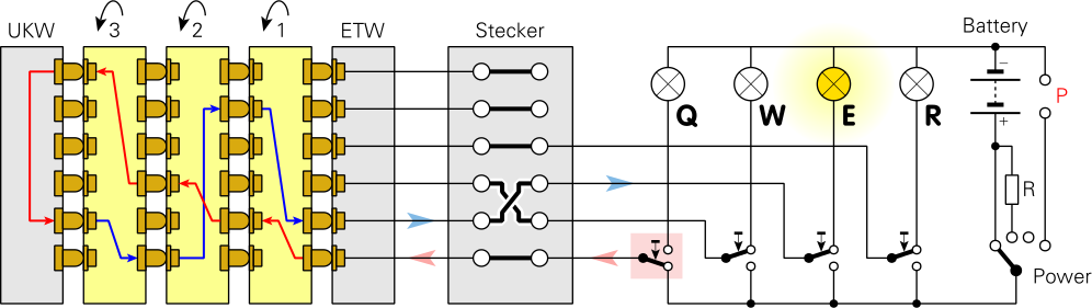
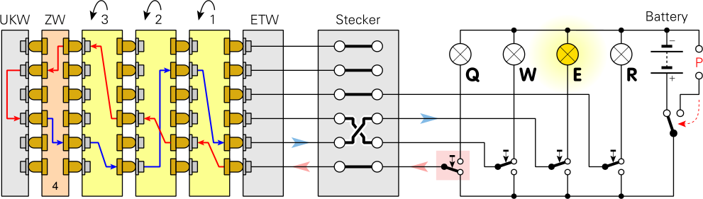
The Enigma uses quite a simple circuit: basically a battery, a number of switches and some bulbs, with the wiring changing which switch is connected to which bulb. In the diagram, the Q key has been pressed, connecting it to the battery. This is wired through the Steckerbrett plugboard (here no plug is fitted, so it is wired straight through) to the ETW entry wheel. The entry wheel was wired differently on many older Enigma models, but on the military models simulated here it is wired straight through, A to A, B to B and so on to Z.
The connection then passes through the wires inside each of the three rotors until it reaches the UKW reflector. Each rotor has a different wiring pattern inside. The reflector is wired in pairs, with thirteen connections sending the current back into the rotors at a different position from the one it came in on. The connection then goes back through the three rotors (by a different route) and back through the ETW. It then makes a second trip through the plugboard (the example shows a Stecker cable fitted, which swaps two of the wires over). Finally it travels through the matching key switch (which is closed, as only one key can be pressed at a time) to a bulb, E in this example, and back to the battery.
Wiring the Enigma up this way, with the reflector, had a couple of important consequences. First, it didn’t need a different wiring system to decipher a message. As long as the settings were identical, typing one letter always gave the same result, and resetting the machine and typing that result gave back the original letter. The downside is that Enigma can never light the same letter as the key pressed, a fact very much used by the codebreakers, first in Poland and then at Bletchley Park, to break this machine.
Note also that when a key is pressed, but before the circuit is connected, the right-hand rotor turns one position, changing the connections and so the route the current takes. At a set point, once every 26 letters, a notch on the rotor pushes the next rotor on one step, and the same again for the third rotor. This means typing the same letter Q will most likely give a different letter each time.
The rotors
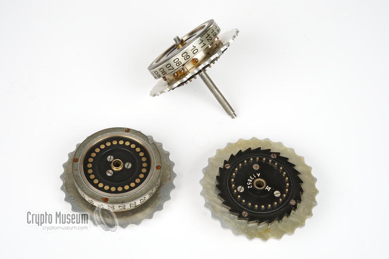
The rotors were central to Enigma’s job of enciphering messages. Simply swapping each letter of the alphabet for another is not a very secure cipher and is easily broken. With Enigma, each time a key is pressed one or more of the rotors moves on a step, changing the wiring in the scrambler, so even typing the same letter over and over gives many different letters out.
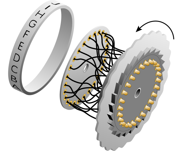
On the most common Enigma rotors, each rotor had 26 positions, numbered 1–26 or lettered A–Z around the tyre. A set of 26 sprung pins on one side was wired to a set of flat contacts on the other, and each rotor, numbered in Roman numerals, had different wiring. Each rotor also had a ring with at least one notch at a certain letter around the edge. The number or letter tyre and the notch ring moved together and could be turned, separately from the wiring, to any of 26 positions. On the Enigma I rotors this was done by releasing a sprung pin that let the tyre turn. On the later M1–M4 rotors this was replaced by a pair of levers which, pressed together, released the tyre.
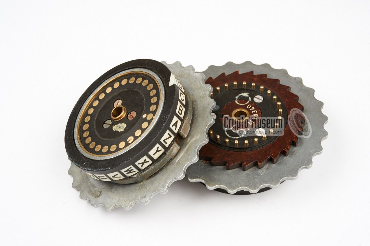
In the wiring tables below, the letter next to the notch is shown, as well as the letter shown in the window just before the rotor steps the next one on. They differ because the pawl that drops into the notch sits several steps back behind the rotors rather than on top.
Enigma I rotor wiring
| Wheel | ABCDEFGHIJKLMNOPQRSTUVWXYZ | Notch | Turnover | Notches |
|---|---|---|---|---|
| ETW | ABCDEFGHIJKLMNOPQRSTUVWXYZ | |||
| I | EKMFLGDQVZNTOWYHXUSPAIBRCJ | Y | Q | 1 |
| II | AJDKSIRUXBLHWTMCQGZNPYFVOE | M | E | 1 |
| III | BDFHJLCPRTXVZNYEIWGAKMUSQO | D | V | 1 |
| IV | ESOVPZJAYQUIRHXLNFTGKDCMWB | R | J | 1 |
| V | VZBRGITYUPSDNHLXAWMJQOFECK | H | Z | 1 |
| UKW-A | EJMZALYXVBWFCRQUONTSPIKHGD | |||
| UKW-B | YRUHQSLDPXNGOKMIEBFZCWVJAT | |||
| UKW-C | FVPJIAOYEDRZXWGCTKUQSBNMHL |
Enigma M4 rotor wiring
| Wheel | ABCDEFGHIJKLMNOPQRSTUVWXYZ | Notch | Turnover | Notches |
|---|---|---|---|---|
| ETW | ABCDEFGHIJKLMNOPQRSTUVWXYZ | |||
| I | EKMFLGDQVZNTOWYHXUSPAIBRCJ | Y | Q | 1 |
| II | AJDKSIRUXBLHWTMCQGZNPYFVOE | M | E | 1 |
| III | BDFHJLCPRTXVZNYEIWGAKMUSQO | D | V | 1 |
| IV | ESOVPZJAYQUIRHXLNFTGKDCMWB | R | J | 1 |
| V | VZBRGITYUPSDNHLXAWMJQOFECK | H | Z | 1 |
| VI | JPGVOUMFYQBENHZRDKASXLICTW | HU | ZM | 2 |
| VII | NZJHGRCXMYSWBOUFAIVLPEKQDT | HU | ZM | 2 |
| VIII | FKQHTLXOCBJSPDZRAMEWNIUYGV | HU | ZM | 2 |
| Beta | LEYJVCNIXWPBQMDRTAKZGFUHOS | |||
| Gamma | FSOKANUERHMBTIYCWLQPZXVGJD | |||
| UKW-b (thin) | ENKQAUYWJICOPBLMDXZVFTHRGS | |||
| UKW-c (thin) | RDOBJNTKVEHMLFCWZAXGYIPSUQ |
The stepping mechanism
When a key is pressed, and before the circuit is connected, a large pivoted lever is pushed down, which pushes up on a bar at the back of the machine. On this bar are three sprung pawls, which rise and push on one or more of the toothed gears on the right-hand side of each rotor.
The right-hand pawl always drops into the first rotor’s drive gear, so it always pushes that rotor on one step. On the left-hand side of each rotor is a ring with a notch cut out of it (or, on the later M1–M4 rotors, two notches).
The second pawl bridges the gap, with half of it resting on the first rotor’s notch ring and half over the second rotor’s drive gear. If the notch is not next to the pawl, the pawl is held away from the drive gear and the second rotor isn’t driven round. But once every 26 steps the pawl drops into the first rotor’s notch, and so catches the second rotor’s drive gear when the next key is pressed.
The third rotor turns in exactly the same way as the second, moving once for every 26 positions of the second rotor.
The double-stepping anomaly
One oddity in this mechanism makes the middle rotor step twice on successive key presses, rather than the usual once. This is known as the double-stepping anomaly. You can see it happen in Virtual Enigma by fitting rotors III, II and I in that order and setting the rotor start positions to 1, 4 and 17 (or A, D and Q on the M4). Press a key and the fast rotor on the right steps once, and its notch is now in position to turn the middle rotor too. Press a second key: the middle rotor’s notch is now in position to turn the left-hand slow rotor, but what you’ll see is all three rotors, fast, middle and slow, turning yet again, so the middle rotor has turned twice.
You can see this in more detail in this close-up video. Watch as the first rotor moves setting 4 past the pawl. The first time is a single step as normal; the second time setting 4 comes past, you should see the double step on the middle rotor.
The Steckerbrett
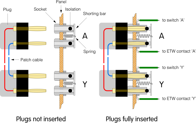
The military Enigma machines (Enigma I and Enigma M1–M4) had a Steckerbrett (plugboard) at the front, behind a hinged panel. It allows any two letters to be swapped by plugging a cable between two of the marked sockets. Each plug had two pins, one thick and one thin, so it could only be fitted one way up. Generally 10 cables were used at a time, swapping twenty of the twenty-six letters in pairs. For example, a cable between A and S would turn an A into an S and an S into an A.
The plugboard varied a little between models: the Enigma I had letters against each socket while the Enigma M1–M4 had numbers, but both worked the same way. For unknown reasons, the pins on the Kriegsmarine models (M1–M4) were around 4 mm longer than those on the Enigma I, making them incompatible. The front wooden panel was mounted so that closing it pushed all the plugs fully home, making sure the connections were made properly.
The Steckerbrett makes a huge difference to the number of possible settings for Enigma: with 10 cables, it multiplies the number of possible settings by 150 million million.
Next: how to use Virtual Enigma.